
Breastshot Waterwheel & Heat – Project Case Study
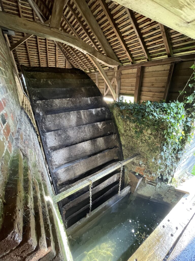
A mid‑to‑late 19th‑century breastshot waterwheel in rural Oxfordshire is being restored and upgraded to provide continuous renewable heat for an attached property.
Recent work has completed several planned upgrades to the waterwheel and heat generation system. The control gate is now fully automated, three severely damaged buckets have been replaced, and enhanced monitoring has been installed to track wheel balance and support automated heat generation.
As much of the UK and Europe experiences a summer heatwave, work continues on a very different heat story in Oxfordshire: adapting a pre-1880s waterwheel to generate low-carbon heat for practical use. While outside temperatures are high, the focus here remains on year-round heat resilience — particularly through the colder months, when heating demand is at its greatest.
The wheel, originally part of a corn mill, had seized and remained stationary for many years. Rather than preserving it as a static heritage feature, the owner has chosen to return it to productive use — not for electricity generation, but for direct mechanical‑to‑thermal conversion (a shaft‑driven heat generator rather than an electrical generator).
This project is part of Rotaheat’s programme to support the adaptation of heritage and modern water‑power assets for low‑carbon heat. While this installation is in the UK, the principles apply to mills across Europe and other regions where functional hydraulic infrastructure remains under‑utilised.
Project Objectives
- Restore the wheel to reliable 24/7 mechanical operation
- Maintain historic integrity wherever possible
- Deliver approximately 10kW of sustained thermal output
- Achieve a levelised cost of heat below 2 p/kWh
- Reduce carbon intensity to below 1 gCO₂/kWh
For context, conventional gas heating typically carries a carbon intensity in the region of 180–200 gCO₂/kWh.
Background: Initial Wheel Release (Early 2026)
When first documented in late 2025, the 5.2-metre wheel was fully seized, with steel piling jammed into the buckets to prevent rotation. Teme Valley Heritage Engineers led the first phase of work, completed in early 2026, focused solely on:
- freeing the seized wheel using traditional millwrighting methods
- returning the wheel to rotation for the first time in many years
This preparatory work provided the foundation for the structural and mechanical upgrades that followed. With the assurance that the waterwheel could reliably rotate, the project moved into strengthening the surrounding structure and preparing the drivetrain for continuous operation.
Structural Repairs and Mechanical Preparation (April 2026)
With the waterwheel turning again, April 2026 saw a coordinated programme of structural and mechanical work to stabilise the installation and prepare the drivetrain for continuous 24/7 operation:
- Repair of a fractured spoke on one of the steel rims
- Brickwork repairs within the wheel pit to restore structural integrity
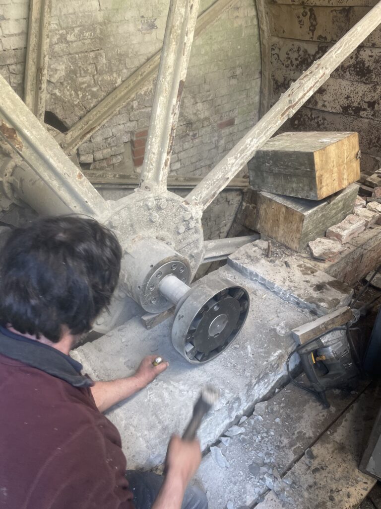
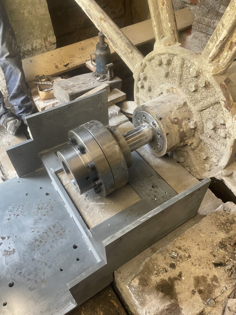
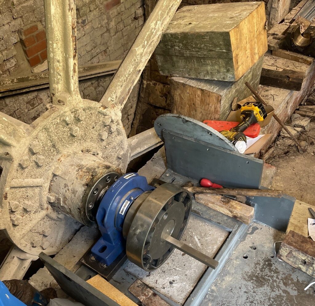
- Machining and installation of a new stub shaft on the original wheel shaft
- Installation of a precision‑engineered steel base platform over the original stone plinth
- Fitting of new SKF Cooper split bearings to support continuous rotation
- Installation of a high-capacity flexible coupling, rated for up to 13,000 Nm of torque, to safely transfer mechanical power to the heat subsystem
- General mechanical preparation, including checking alignment, for sustained operation under load
These upgrades established the mechanical interface between the historic wheel and the modern heat-generation equipment. Together, the new stub shaft, bearings, baseplate and flexible coupling created the drivetrain needed to transfer power from the wheel into the heat-generation subsystem.
These works collectively mark the transition from heritage restoration to controlled mechanical power delivery suitable for renewable heat generation.
May–June Update: Heat Subsystem Installation and Infrastructure Upgrades
With the mechanical interface complete, May and June’s focus was on installing and integrating Rotaheat’s heat-generation subsystem.
The waterwheel is now coupled to a Rotaheater Pico, via a Flender gearbox, enabling the wheel’s rotational power to be converted directly into thermal energy.
Alongside this, a new sensor and controller package has been installed, providing:
- real-time thermal output monitoring
- live efficiency tracking
- system diagnostics
- control capability to manage heat generation in response to site demand
This control capability is central to understanding performance and optimising system efficiency.
Additional infrastructure renovation works have also been completed:
- installation of a new bypass sluice gate, replacing a substantially rotten predecessor
- further rendering and repair of brickwork within the wheel chamber
- capture and relocation of over 400 freshwater crayfish from the millpond and tail race ahead of works
These parallel works improve long-term reliability, preserve the surrounding heritage fabric and support the wider environmental management of the site.
July-August Update: Balance, Automation and Monitoring
With the system operating and producing heat whilst in a regional drought, July and August focused on verifying the automation and analysing collected data to identify priority improvement actions.
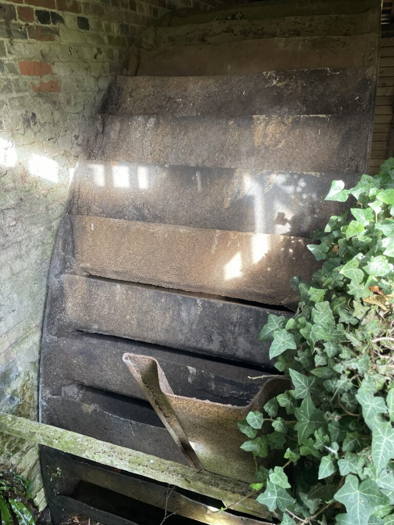
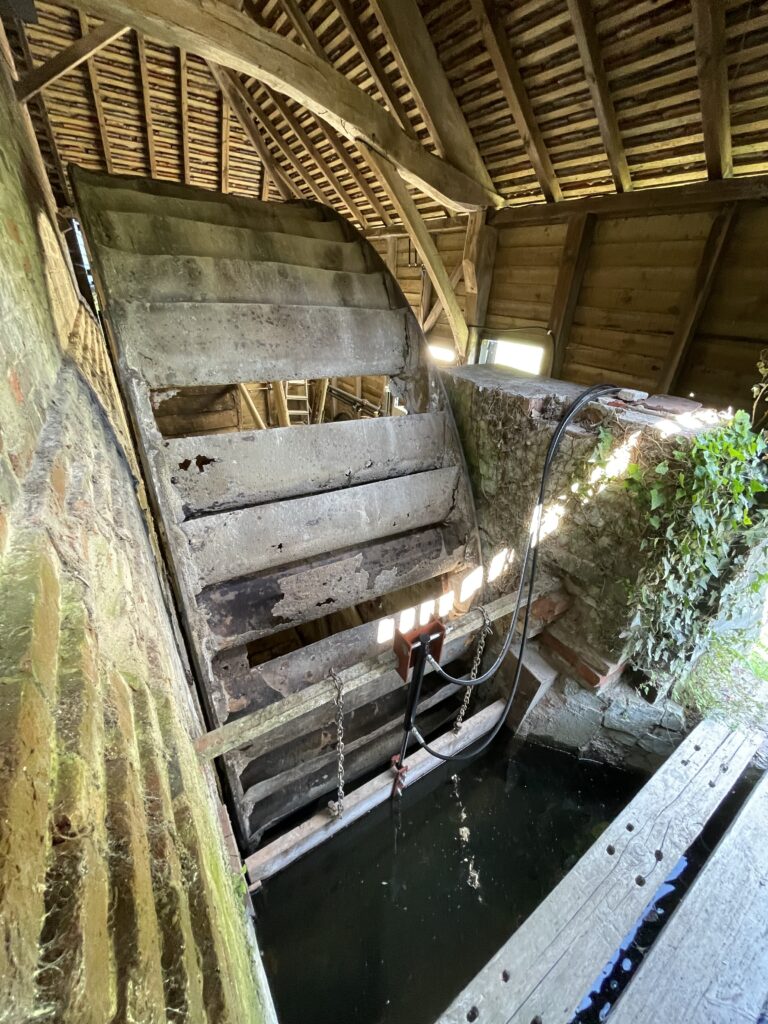
Until this year, the wheel had largely remained static in recent years. Water had continued to flow into some wrought iron buckets, leading selected buckets to rust over time, and mineral deposits built up in some other buckets.
Three rusted buckets were fully removed, and whilst awaiting the fabrication of new buckets, the opportunity was taken to analyse the effects of the damaged buckets and wheel imbalance.
The instantaneous speed of the wheel changed significantly during each revolution, with a consequential change in the measured power.
The imbalance effects were dramatic; the wheel’s speed would drop 74% below the average speed and peak 95% above the average speed. A ‘double dip’ in speed was attributed to the missing buckets, with the variance in speed exacerbated by a build up in mineral deposits on one section of the wheel.
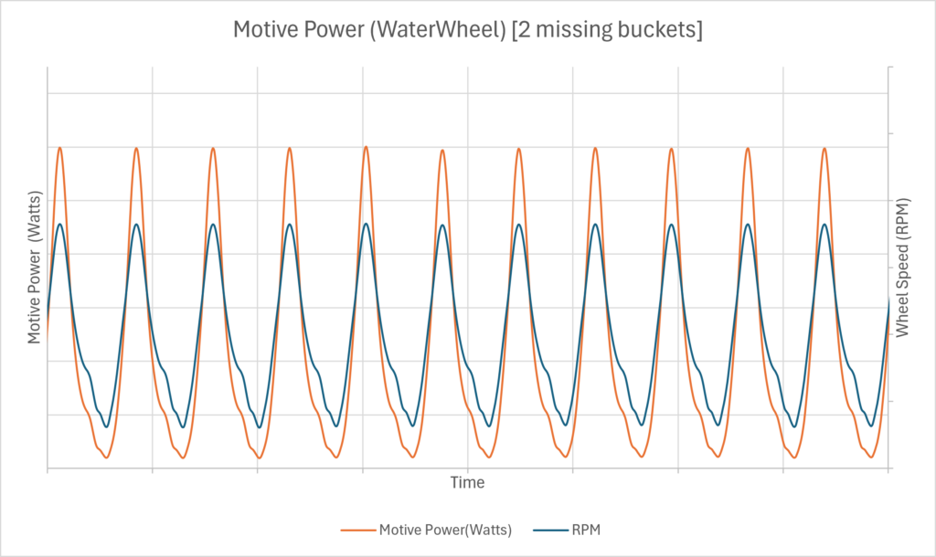
With newly fabricated buckets installed, the variation in speed notably dropped, with some residual rebalancing required. Other completed pieces of work included:
- Applying a top coat of protective paint to the base frame and flexible coupling
- Installing a hydraulic piston to automate raising and lowering of the control gate
- Validating automated control gate operation in response to changes in demand for heat
- Clearing the tail race of accumulated rubble and reeds to improve water flow and allow the wheel to turn more efficiently
- Applying additional insulation to reduce thermal losses
With water flows impacted by current drought conditions in the area, the system has not yet reached its expected peak output. Currently, output is sufficient to meet the reduced heat demand of summer, with output peaking at about 4kW of heat. Initial summer operation:
- Demonstrates a system efficiency typically varying between 92-95%
- Supports a modelled carbon intensity of approximately 5 gCO₂e/kWh
- Supports a modelled levelised cost of heat below the cost of gas.
Next Steps: Further Monitoring and Analysis
With the system operating in a 24/7 unattended mode, our attention will now focus on further monitoring, analysis and optimisation, including:
- Refine confidence in projected generation, carbon and financial benefits as the summer season transitions towards cooler and wetter conditions
- Automate identification of performance irregularities
Looking forward, wetter and cooler weather will provide an opportunity to validate the system’s capability against an increased demand for heat.
Why Waterwheels for Heat?
Many historic mills retain viable hydraulic infrastructure but lack an economically compelling route back into use. Direct heat generation offers clear advantages:
- no grid connection constraints,
- no reliance on export tariffs,
- low conversion losses,
- very low operating costs and
- near‑zero operational carbon intensity.
This project shows how heritage hydro assets can materially reduce heating costs while supporting local decarbonisation goals.
Follow the Project
The next update will report on refinements to the projected long-term performance projects against the original design expectations, including:
- thermal output
- carbon intensity
- levelised cost of heat
If you own or manage a site with an existing waterwheel or hydro turbine and are exploring options to reduce heating costs, we would welcome a conversation.